Start up & homing
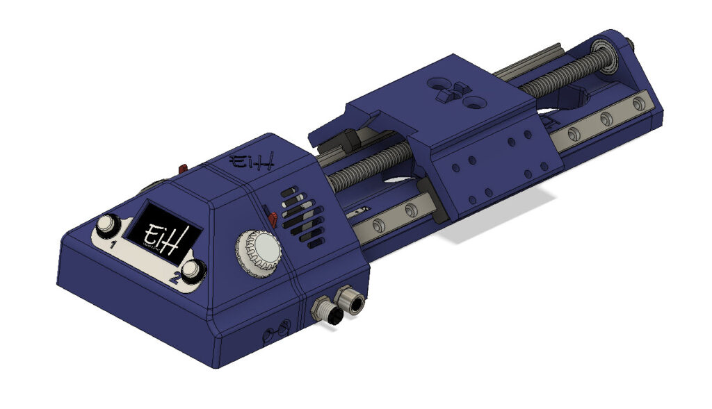
Prior to power up, you must verify that the camera carrier (CC) is within homing range, this area is marked on the chassis.
At power up you are prompted to perform a automatic homing procedure. When the homing procedure is activated the CC moves rapidly a set distance in positive direction – thereafter it moves in negative direction while searching for homing reference. Once the homing reference is found, the speed is reduced and the CC is moved to axis zero position. The system is now ready for use.
Setting of global parameter are possible prior to above mentioned homing sequence, but all other settings are prohibited.
Global Settings
The following settings can be accessed in the global settings menu:
- Focus increment – movement of camera carrier for each step in mm
- Dwell timer – delay from camera carrier is in position to the trigger is activated, in ms. This is to allow camera movements to settle prior to taking the picture
- Max Speed – system max speed
- Acceleration – system acceleration
- Trigger Duration – how long the trigger signal is keep high
- Shutter speed comp. – compensating for shutter speed, additional delay added after trigger is activated – to allow slow shutter speeds to be utilized. Unit in ms.
- Num. Pics. – number of pictures taken at each position
- Start Delay – delay from camera carrier is in position for first photo until the shutter is activated. Valid for first photo only. Unit in ms.
- Shutter Lag – delay between activating focus and shutter, focus is always activated first.
- Audio feedback – setting for audible feeback
- LED feedback – settings for LED feedback
- HighRes – mode for higher resolution
- Op. Mode – mode for operation, auto or semi-auto
(some settings described will probably be moved out of global settings to another menu at a later time – this in conjunction with the possibility to store different profiles)
Manual Mode
Enter manual mode by pressing and holding the rotary encoder for approx 1,5 seconds. You can now manually jog the CC by rotating the rotary encoder. Pressing the rotary encoder swiftly will toggle between fast and slow jog mode.
By use of soft keys you can register start & end position and also manually trigger the shutter.
Pres and hold rotary encoder for approx 1,5 second to exit manual mode.
Setting Start & End Positions
To be able to execute a sequence the system needs to know the start & end position, with this information- in combination with the global settings, the system will calculate the theoretical travel distance and number of steps needed.
To set the start & end position you need to enter manual mode and jog the CC to your desired start or end position. Use the screen or the viewfinder of your camera to verify that the desired area is within focus and use the corresponding soft key to registrer if this is the start or end position.
If the registered end position is greater than the registered start position, the sequence runs in positive direction, if the registered end position is less than the registered start position, the sequence runs in negative direction.
Please note that if the theoretical travel distance is not divisible by the selected Focus Increment, the system will adjust the number of steps in a maner that makes sure that the en position is reached. This means that the actual end position may exceed the registered end position by the amount up to one Focus Increment. If this results in an end position that is out of range, you will be informed and prompted to redefine your end position.
Automatic Mode
Automatic mode is selected in Global Setting.
Automatic mode perform in the following way:
- CC moves 1 mm beyond start position, with respect to the travel direction
- CC moves to start position
- Dwell time for settling movements
- Trigger camera
- Optional delay for slow shutter speed
- Loops two last steps if multiple pictures are to be taken
- Moves to next position
- Loops through five last steps until actual end position is reached
- Returns to start position
Semi-Automatic Mode
Semi-Automatic mode is selected in Global Setting.
This is a semi-automatic sequence that perform in the following way:
- CC moves 1 mm beyond start position, with respect to the travel direction
- CC moves to start position
- Dwell time for settling movements
- Waiting for user to activate camera trigger
- Optional delay for slow shutter speed
- Loops two last steps if multiple pictures are to be taken
- Moves to next position
- Loops through five last steps until actual end position is reached
- Returns to start position
This mode is use full in situations when you i.e. are dealing with variable naturally light or other variabels where you want manual control for when the camera shutter is triggered.
As of February 2023 – functionality shown in red & italic is not yet fully implemented in the current firmware, but needed hardware is integrated.